
Bend Deduction Calculator
Set the angle, thickness and punch radius (or grab the flange in the drawing and bend it) and get the bend deduction and the flat blank length, worked out from LCNW’s press-brake bend tables.
- Bend allowance
- 0.284
- Outside setback
- 0.250
- K-factor
- 0.446
- Bend line from edge A
- 1.892
- Included angle
- 90°
Your bend
Flanges are outside dimensions to the virtual sharp, where the outer faces would meet.
For reference only. This doesn’t guarantee the part can be formed; tooling, grain and material change the result. Ask us about your part →
Bend deduction, explained
Bend deduction (BD) is how much shorter a flat sheet metal blank is than its outside flange dimensions added together. Measure each flange on the outside to the corner, add them up, subtract the bend deduction, and you have the length to cut: flat blank = A + B − BD.
It exists because metal doesn’t fold at a sharp corner. It wraps around the punch: the outside of the bend stretches, the inside compresses, and the corner comes out round. Your drawing measures flanges to the virtual sharp, the point where the outside faces would meet if the corner were sharp. The real part never reaches that point, so a blank cut to A + B comes out too long. Bend deduction is the correction.
The bend deduction formula
Four things decide the bend deduction: the bend angle (θ), the material thickness (t), the inside radius (r), and where the neutral axis sits inside the thickness. The neutral axis is the layer that neither stretches nor compresses. Its position is written as a fraction of the thickness, the K-factor.
Textbook calculators stop there and ask you to guess K. This one starts from what the press brake actually does. Bend deduction comes from LCNW’s brake chart as BD = T × t + R × r, where T and R are measured factors for each degree from 1° to 147° (at 90°, T = 1.301 and R = 0.428). The bend allowance, setback and K-factor in the results are worked backward from that number, so they all agree with each other and with the brake.
A handy shortcut from the same chart: at 90° with the inside radius equal to the thickness, the bend deduction is about 1.73 × t.
Worked example: an 11 gauge bracket
Take an L-bracket in 11 gauge mild steel (t = 0.120″), bent to 90° with a 0.120″ inside radius. Flange A is 3.000″ and flange B is 1.500″, both measured outside to the virtual sharp.
- Bend deduction: 1.301 × 0.120 + 0.428 × 0.120 = 0.207″
- Flat blank: 3.000 + 1.500 − 0.207 = 4.293″
- Outside setback: (0.120 + 0.120) × tan 45° = 0.240″
- Bend allowance: 2 × 0.240 − 0.207 = 0.273″, which puts K at 0.45
- Bend line: 3.000 − 0.240 + 0.273 ÷ 2 = 2.896″ from edge A
Open this example in the calculator to check the numbers or change them.
Bend deduction chart
Bend deductions for common sheet and plate thicknesses with the inside radius equal to the thickness, a common starting point for air bending. The 90° column is the one most shops reach for.
| Material | Thickness | 30° | 45° | 60° | 90° | 120° | 135° |
|---|---|---|---|---|---|---|---|
| 16 ga | 0.060 | 0.019 | 0.031 | 0.048 | 0.104 | 0.231 | 0.388 |
| 14 ga | 0.075 | 0.024 | 0.039 | 0.060 | 0.130 | 0.288 | 0.485 |
| 12 ga | 0.105 | 0.033 | 0.055 | 0.084 | 0.182 | 0.404 | 0.680 |
| 11 ga | 0.120 | 0.038 | 0.063 | 0.096 | 0.207 | 0.462 | 0.777 |
| 10 ga | 0.135 | 0.042 | 0.070 | 0.108 | 0.233 | 0.519 | 0.874 |
| 3/16″ | 0.188 | 0.059 | 0.098 | 0.149 | 0.324 | 0.721 | 1.214 |
| 1/4″ | 0.250 | 0.079 | 0.131 | 0.199 | 0.432 | 0.962 | 1.618 |
Bend deduction vs. bend allowance
They’re two routes to the same blank, starting from different measurements:
| Bend deduction | Bend allowance | |
|---|---|---|
| Measures from | Outside dimensions to the virtual sharp | The flat portions on either side of the bend |
| Blank | A + B − BD | (A − OSSB) + (B − OSSB) + BA |
| Best when | Your print dimensions the outside of the part (most do) | Your CAD works from the neutral axis and K-factor |
Since BD = 2 × OSSB − BA, both give the same answer. The calculator shows both.
What K-factor should I use?
K is where the neutral axis sits, measured from the inside face as a fraction of thickness. It usually falls between about 0.3 and 0.5: lower for tight radii and hard materials, higher as the radius grows. Air-bent steel with r = t comes out near 0.45 from LCNW’s chart. If your CAD software asks for a K-factor, enter the one this calculator reports for your thickness and radius, and its flat patterns will match ours.
Using the calculator
- Set the angle. Type it, use the slider or a preset, or drag the handle on the end of flange B in the drawing. This is degrees of bend: 90° makes a right angle, and the included angle is shown in the results.
- Enter the thickness, or pick a common gauge.
- Set the inside radius. It follows the thickness until you change it. Use your punch radius, or your shop’s expected air-bend radius.
- Add flange A and B, measured outside to the virtual sharp, to get the flat blank and where to mark the bend line.
Everything recalculates as you type. Switch between inches and millimeters at any time; the factors don’t depend on units. Copy link to this bend puts the whole setup in the URL so you can send it to a customer or the shop floor.
For parts with several bends, measure each flange to its virtual sharps and subtract one bend deduction per bend: blank = sum of the outside flange lengths − sum of the bend deductions.
Tips from the press brake
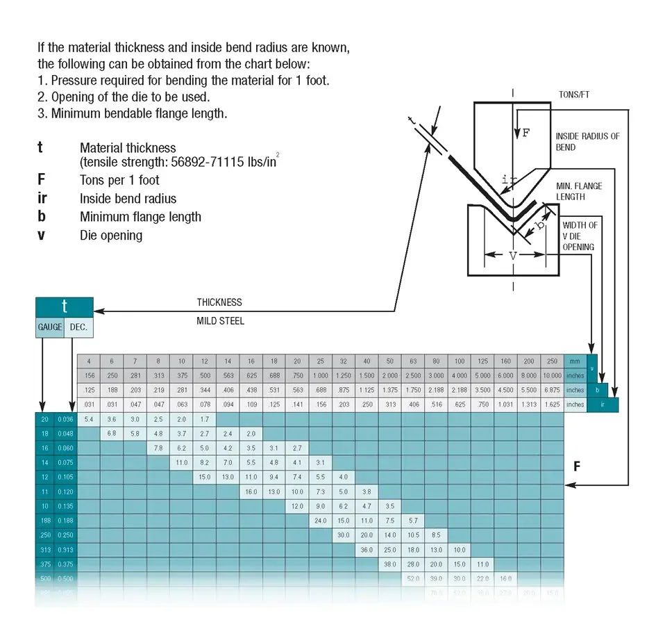
- The die sets the radius. In air bending the inside radius comes from the V-die opening, not the punch tip, roughly 15–16% of the opening in mild steel. Ask your shop which die they’ll use before you lock a flat pattern.
- Mind the minimum flange. A flange shorter than the die can support won’t form cleanly. The calculator warns you when a flange is shorter than the setback.
- Springback is the operator’s job. The brake over-bends to land on your angle. Bend deduction depends on the finished angle and radius, so calculate with the angle you want, not the angle the brake travels to.
- Bend across the grain when you can, especially on tight radii in harder alloys, to avoid cracking on the outside of the bend.
- Treat it as a starting point. Material lot, tooling wear and grain all move the result a few thousandths. For production, bend a test piece and adjust.
Where shops use it
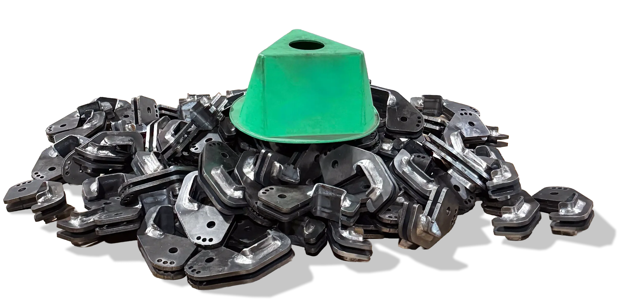
Any formed sheet metal part needs a blank sized this way: electrical enclosures and panels, HVAC ductwork and housings, architectural metal like trim, fascia and bent plate, brackets and weldment components for automotive, agricultural and construction equipment, and appliance and machine housings. LCNW cuts and forms all of these in Auburn, Washington. If you’d rather hand us the drawing, we’ll do the math and make the parts.
Frequently asked questions
What is the bend deduction for a 90° bend?
How do I calculate bend deduction?
What’s the difference between bend deduction and bend allowance?
Is the bend angle the same as the included angle?
Does the calculator work in millimeters?
Why doesn’t my formed part match the calculation?
This calculator is a reference, not a guarantee that a part can be formed. Tooling, grain and material change the result. Ask LCNW about your part →